Inductors, also known as coils, chokes, windings or reactors are passive electronic components that resist changes in current flow. They consist of a conductor, usually a coil of wire, wound around a core material. When current flows through an inductor, it generates a magnetic field that stores energy. This stored energy can be released when the current changes, helping to stabilize and control the flow of electrical signals in a circuit.
Graphic Symbols for Inductors, Coils, Chokes, and Windings
There are many different symbols used to represent inductors. I have done a lot of research in regulatory documents and have compiled a table of current and validated graphical symbols for inductors, coils, chokes, and windings.
See also: Transformer symbols ►
| Inductor Symbol | Description | Notes |
|---|---|---|
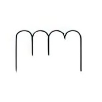
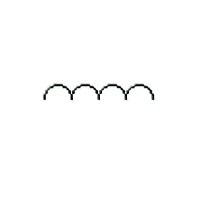
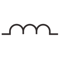
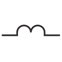
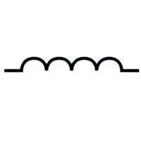 | Name: Coil, general symbol Alternative names: Winding, general symbol; Air core inductor; Choke. Source: IEC 60617-2019, IEEE Std 315-1993 | A1, A2, A3 |
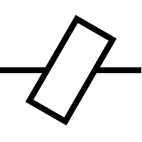
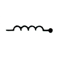 | Name: series inductor and path open. Source: IEEE Std 315-1993 | A4 |
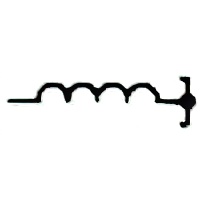 | Name: series inductor and path short-circuited. Source: IEEE Std 315-1993 | A4 |
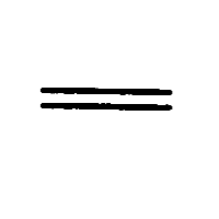 | Name: Magnetic core of inductor or transformer Source: IEEE Std 315-1993 | A5 |
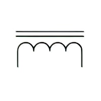
 | Name: Inductor with magnetic core. Source: IEC 60617-2019 | – |
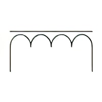
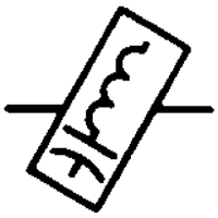
 | Name: Magnetic-core inductor. Alternative names: Telephone loading coil; Iron core inductor Source: IEEE Std 315-1993 Note: If necessary to show a magnetic core. | – |
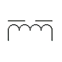 | Name: Inductor with gap in magnetic core. Source: IEC 60617-2019, IEEE Std 315-1993 | – |
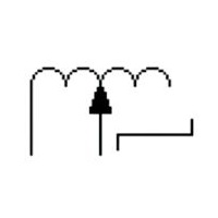
 | Name: Inductor with fixed tappings. Remarks: The symbol is shown with two tappings (taps). Source: IEC 60617-2019 | – |
 | Name: Coaxial choke with magnetic core. Source: IEC 60617-2019 | – |
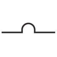
 | Name: Reactor, general symbol. Form 1. Alternative name: Choke. Source: IEC 60617-2019 | A6 |
 | Name: Reactor, general symbol. Form 2. Alternative name: Choke. Source: IEC 60617-2019 | A1, A6, A7 |
 | Name: Inductor, continuously variable. Remarks: The symbol is shown with magnetic core. Source: IEC 60617-2019 | – |
 | Name: Inductor with moveable contact, variable in steps. Source: IEC 60617-2019 | – |
 | Name: Variometer. Source: IEC 60617-2019 | – |
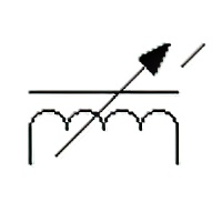
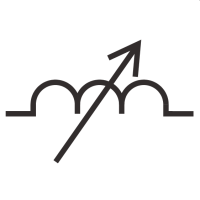
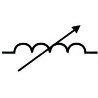 | Name: Adjustable or continuously adjustable inductor Source: IEEE Std 315-1993 | – |
 | Name: Adjustable inductor. Source: IEEE Std 315-1993 | – |
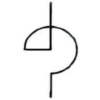
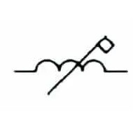 | Name: Coil operated flag indicator. Source: IEEE Std 315-1993 | – |
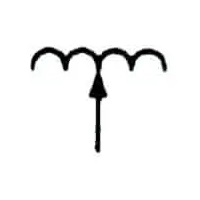
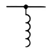 | Name: Shunt inductor. Source: IEEE Std 315-1993 | – |
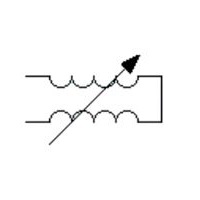
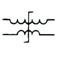 | Name: Transductor element, assembled. Alternative names: saturable-core inductor, saturable-core reactor Source: IEEE Std 315-1993 | A8 |
 | Name: Inductance, high Source: IEC 60417-2020 | A9 |
 | Name: Inductance, medium Source: IEC 60417-2020 | A10 |
 | Name: Inductance, low Source: IEC 60417-2020 | A11 |
 | Name: Inductance, variable Source: IEC 60417-2020 | A12 |
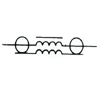
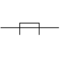
 | Name: Carrier line trap (carrier elimination filter) Source: IEEE Std 315-1993 | A13 |
 | Name: Ferrite bead ring (IEEE style) Alternative names: Ferrite block; Ferrite core; Ferrite ring; EMI filter; Ferrite choke. Source: IEEE Std 315-1993 | A14 |
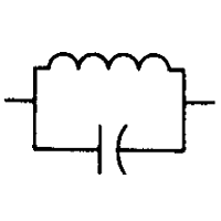
 | Name: Ferrite bead ring with equivalent circuit (LC network) shown Source: IEEE Std 315-1993 | – |
 | Name: Ferrite bead (IEC style) Remarks: Ferrite bead is shown on a conductor. Source: IEC 60617-2019 | – |
Application Notes
A1: If it is desired to show that there is a magnetic core, a single line may be added parallel to the symbol. The line may be annotated to indicate non-magnetic materials; it may be interrupted to indicate a gap in the core.
A2: The number of half-circles may be varied to suit the application.
A3:![]() – This symbol is deprecated by IEEE Std 315 and should not be used on new schematics.
– This symbol is deprecated by IEEE Std 315 and should not be used on new schematics.
A4: Commonly used in coaxial and waveguide diagrams.
A5: Not to be used unless it is necessary to identify a magnetic core.
A6: Two forms of symbols are given for the same type of transformer:
- Form 1 uses a circle to represent each winding. Its use is preferably restricted to single-line representation. Symbols for transformer cores are not used with this form.
- Form 2 uses symbol to represent each winding. The number of half-circles may be varied to differentiate between winding.
A7: The instantaneous voltage polarities may be indicated in form 2 of the symbol. IEC 60375 gives a method of indicating the instantaneous voltage polarities of coupled electric circuits. For an example, see 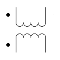 .
.
A8: When windings are separated on a drawing, suitable indication shall be provided to show that they are on the same core. If essential for clarity, the magnetic core symbol may be added where applicable.
A9: To identify inductance or used with other inductance symbols, high inductance, e.g. on arc welding equipment.
A10: To identify medium inductance connection, function or control, e.g. on arc welding equipment.
A11: To identify low inductance connection, function or control, e.g. on arc welding equipment.
A12: To identify a variable inductance function or control, e.g. on arc welding equipment.
A13: If it is essential to indicate the following characteristics, the specified letter or letters may be inserted within or placed adjacent to the symbol.
- 2f – Two frequency
- WB – Wide band
- NB – Narrow band
A14: If equivalent circuits must be shown within the symbol, the size or the aspect ratio of the original symbol may be altered providing its distinctive shape is retained.
Last Updated on: October 27, 2023
