Download
1 / 23
290 likes | 603 Views
Common-Base (CB) Amplifier. DC biasing Calculate I C , I B , V CE Determine related small signal equivalent circuit parameters Transconductance g m Input resistance r π Midband gain analysis Low frequency analysis Gray-Searle (Short Circuit) Technique

E N D
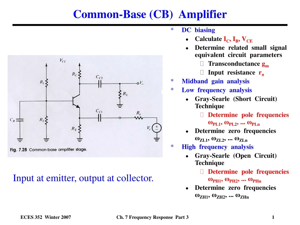
Common-Base (CB) Amplifier • DC biasing • Calculate IC, IB, VCE • Determine related small signal equivalent circuit parameters • Transconductance gm • Input resistance rπ • Midband gain analysis • Low frequency analysis • Gray-Searle (Short Circuit) Technique • Determine pole frequencies ωPL1, ωPL2, ... ωPLn • Determine zero frequencies ωZL1, ωZL2, ... ωZLn • High frequency analysis • Gray-Searle (Open Circuit) Technique • Determine pole frequencies ωPH1, ωPH2, ... ωPHn • Determine zero frequencies ωZH1, ωZH2, ... ωZHn Input at emitter, output at collector. Ch. 7 Frequency Response Part 3
CB Amplifier - DC Analysis (Same as CE Amplifier) • GIVEN: Transistor parameters: • Current gain β= 200 • Base resistance rx = 65 Ω • Base-emitter voltage VBE,active = 0.7 V • Resistors: R1=10K, R2=2.5K, RC=1.2K, RE=0.33K • Form Thevenin equivalent for base; given VCC= 12.5V • RTh = RB = R1||R2 = 10K||2.5K = 2K • VTh = VBB = VCC R2 / [R1+R2] = 2.5V • KVL base loop • IB = [VTh-VBE,active] / [RTh+(β +1)RE] • IB = 26 μA • DC collector current IC = βIB IC = 200(26 μ A) = 5.27 mA • Transconductance gm= IC / VT ;VT = kBT/q = 26 mV gm = 5.27 mA/26 mV = 206 mA/V • Input resistancerπ = β / gm = 200/[206 mA/V]= 0.97 K • Check on transistor region of operation • KVL collector loop • VCE = VCC - IC RC - (β +1) IBRE = 4.4 V (okay since not close to zero volts). R1 = 10K R2 = 2.5K RC = 1.2K RE = 0.33K Ch. 7 Frequency Response Part 3
CB Amplifier - Midband Gain Analysis • Construct small signal ac equivalent circuit (set DC supply to ground) • Substitute small signal equivalent circuit (hybrid-pi model) for transistor • Neglect all capacitances • Coupling and emitter bypass capacitors become shorts at midband frequencies (~ 105 rad/s) • Why? Impedances are negligibly small, e.g. few ohms because CC1, CC2, CE ~ few μF (10-6F) • Transistor capacitances become open circuits at midband frequencies • Why? Impedances are very large, e.g. ~ 10’s M Ω because Cπ , Cμ ~ pF (10-12 F) • Calculate small signal voltage gain AVo = Vo /Vs High and Low Frequency AC Equivalent Circuit Ch. 7 Frequency Response Part 3
CB Amplifier - Midband Gain Analysis Iπ βIπ + _ re Ve Equivalent resistance re Voltage gain is less than one ! Ch. 7 Frequency Response Part 3
What Happened to the CB Amplifier’s Midband Gain? • Source resistance Rs = 5K is killing the gain. • Why? Rs >> re = 0.0051 KsoVe/Vs<<1 • Need to use a different signal source with a very low source resistance Rs , i.e. ~ few ohms • Why is re so low? • Vs drives formation of Ve • Ve creates Vπ across rπ • Vπ turns on dependent current source • Get large Ie for small Ve so re =Ve/Ie is very small. + _ re Ve Voltage gain is now much bigger than one ! Ch. 7 Frequency Response Part 3
Analysis of Low Frequency Poles Gray-Searle (Short Circuit) Technique • Draw low frequency AC circuit • Substitute AC equivalent circuit for transistor (hybrid-pi for bipolar transistor) • Include coupling and base capacitors CC1, CC2, CB • Ignore (remove) all transistor capacitances Cπ , Cμ • Turn off signal source, i.e. set Vs= 0 • Keep source resistance RS in circuit (do not remove) • Consider the circuit one capacitor Cx at a time • Replace all other capacitors with short circuits • Solve remaining circuit for equivalent resistance Rx seen by the selected capacitor • Calculate pole frequency using • Repeat process for each capacitor finding equivalent resistance seen and the corresponding pole frequency • Determine the dominant (largest) pole frequency • Calculate the final low pole frequency using Ch. 7 Frequency Response Part 3
Common Base - Analysis of Low Frequency PolesGray-Searle (Short Circuit) Technique Low Frequency AC Equivalent Circuit • Base capacitor CB = 12 μF Vx Ix Iπ Vo + Vπ Vi RxCB _ Ri Ch. 7 Frequency Response Part 3
Common Base - Analysis of Low Frequency PolesGray-Searle (Short Circuit) Technique Input coupling capacitor CC1 = 2 μF Iπ Vo Vπ Ve Vx Ie + _ re Ix Rs Ve Ch. 7 Frequency Response Part 3
Common Base - Analysis of Low Frequency PolesGray-Searle (Short Circuit) Technique • Output coupling capacitor CC2 = 3 μF • Low 3dB frequency VX Vo RC RL Dominant low frequency pole is due to CC1 ! Ch. 7 Frequency Response Part 3
Common Base - Low Frequency Zeros Iπ • What are the zeros for the CB amplifier? • For CC1 and CC2 , we get zeros at ω = 0 since ZC = 1 / jωC and these capacitors are in the signal line, i.e. ZC at ω = 0 so Vo 0. • Consider RB in parallel with CB • Impedance given by • When Z’B , Iπ 0, so gmVπ 0, so Vo 0 • Z’B when s = - 1 / RBCB so pole for CB is at Ch. 7 Frequency Response Part 3
Common Base - Low Frequency Poles and ZerosMagnitude Bode Plot Ch. 7 Frequency Response Part 3
Common Base - Low Frequency Poles and ZerosPhase Shift Bode Plot Ch. 7 Frequency Response Part 3
Analysis of High Frequency Poles Gray-Searle (Open Circuit) Technique • Draw high frequency AC equivalent circuit • Substitute AC equivalent circuit for transistor (hybrid-pi model for transistor with Cπ, Cμ) • Consider coupling and emitter bypass capacitors CC1, CC2, CB as shorts • Turn off signal source, i.e. set Vs = 0 • Keep source resistance RS in circuit • Neglect transistor’s output resistance ro • Consider the circuit one capacitor Cx at a time • Replace all other transistor capacitors with open circuits • Solve remaining circuit for equivalent resistance Rx seen by the selected capacitor • Calculate pole frequency using • Repeat process for each capacitor • Calculate the final high frequency pole using Ch. 7 Frequency Response Part 3
Common Base - Analysis of High Frequency PolesGray-Searle (Open Circuit) Technique High frequency AC equivalent circuit NOTE: We neglect rx here since the base is grounded. This simplifies our analysis, but doesn’t change the results appreciably. Ch. 7 Frequency Response Part 3
Common Base - Analysis of High Frequency PolesGray-Searle (Open Circuit) Technique Ze + _ Ve Replace this with this. • Equivalent circuit for Ze Parallel combination of a resistor and capacitor. Ze Ch. 7 Frequency Response Part 3
Common Base - Analysis of High Frequency PolesGray-Searle (Open Circuit) Technique Turn off signal source when finding resistance seen by capacitor. • Pole frequency for Cπ =17pF Ch. 7 Frequency Response Part 3
Common Base - Analysis of High Frequency PolesGray-Searle (Open Circuit) Technique • Pole frequency for Cμ =1.3pF • Equivalent circuit for Capacitor Cμ= 1.3 pF • High 3 dB frequency = 0 Rs || RE || rπ Dominant high frequency pole is due to Cμ ! Ch. 7 Frequency Response Part 3
Common Base - High Frequency Zeros • What are the high frequency zeros for the CB amplifier? • Voltage gain can be written as • When Vo/Vπ 0, we have found a zero. • For Cμ, we get Vo 0 when ω since the output will be shorted to ground thru Cμ. • Similarly,we get a zero from Cπ when when ω since ZC π = 1/sCπ 0, so the voltage Vπ 0. • Both Cπ and Cμ give high frequency zeros at ω ! Ch. 7 Frequency Response Part 3
Common Base - High Frequency Poles and ZerosMagnitude Ch. 7 Frequency Response Part 3
Common Base - High Frequency Poles and ZerosPhase Shift Ch. 7 Frequency Response Part 3
Comparison of CB to CE Amplifier CE (with RS = 5K) CB (with RS = 5Ω) Midband Gain Low Frequency Poles and Zeros High Frequency Poles and Zeroes Note: CB amplifier has much better high frequency performance! Ch. 7 Frequency Response Part 3
Comparison of CB to CE Amplifier (with same Rs = 5 Ω) CE (with RS = 5 Ω) CB (with RS = 5Ω) Midband Gain Low Frequency Poles and Zeros High Frequency Poles and Zeroes Note: CB amplifier has much better high frequency performance! Ch. 7 Frequency Response Part 3
Conclusions • Voltage gain • Can get good voltage gain from both CE and CB amplifiers. • Low frequency performance similar for both amplifiers. • CB amplifier gives better high frequency performance ! • CE amplifier has dominant pole at 5.0x10⁷ rad/s. • CB amplifier has dominant pole at 7.1x10⁸ rad/s. • Bandwidth approximately 14 X larger! • Miller Effect multiplication of C by the gain is avoided in CB configuration. • Current gain • For CE amplifier, current gain is high AI= Ic / Ib • For CB amplifier, current gain is low AI= Ic / Ie (close to one)! • Frequency dependence of current gain similar to voltage gain. • Input and output impedances are different for the two amplifiers! • CB amplifier has especially low input resistance. Ch. 7 Frequency Response Part 3