
By Mark D. Hagel, PhD, P.Eng., and Monica Guzman, M.Sc., B.Eng.
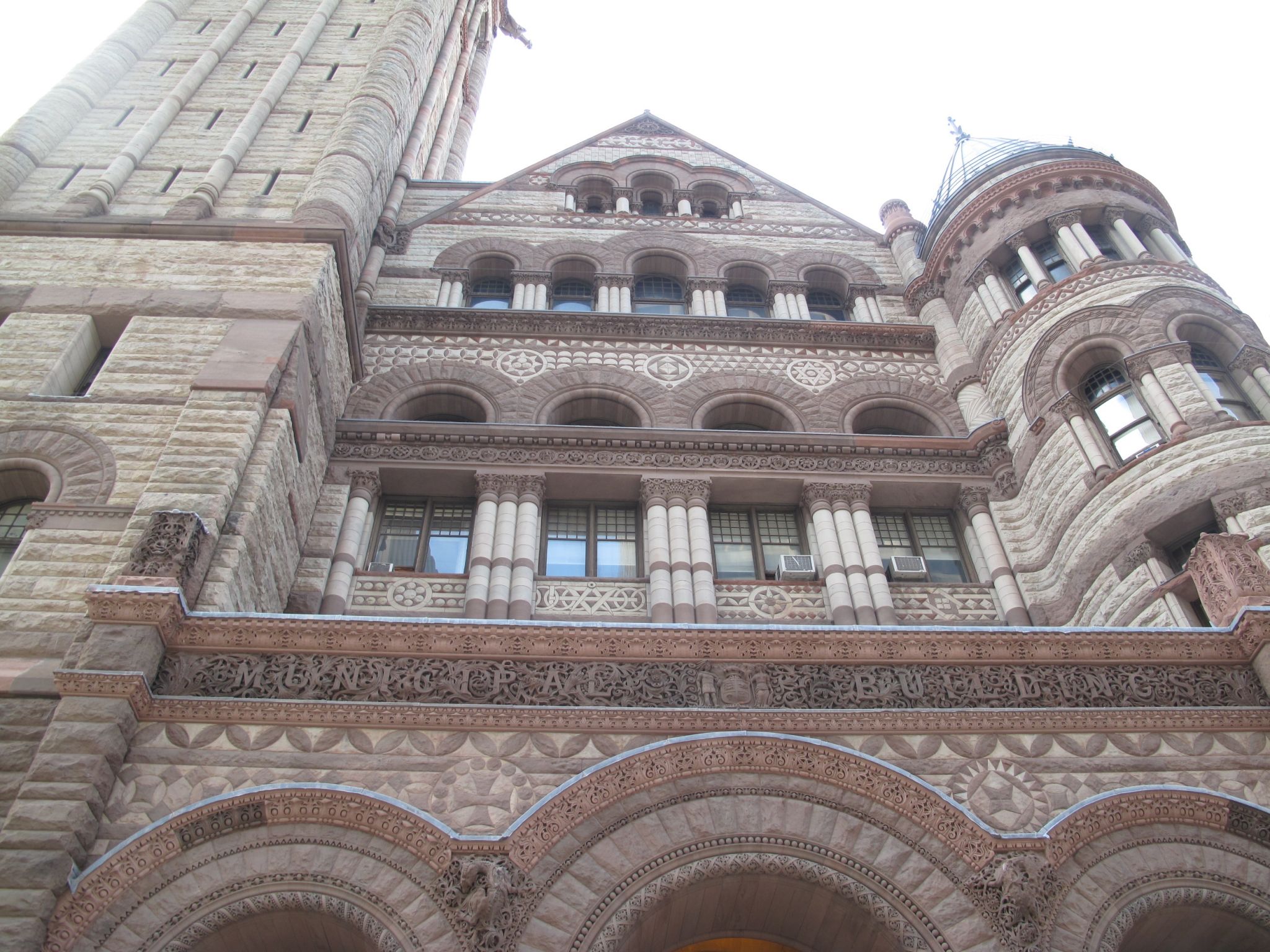
Masonry arches have been constructed around the world for millennia, from the ancient round arches of Egypt and China, to semi-circular Roman and pointed Gothic ones found in Medieval European cathedrals. The first recorded brick arch is believed to have been constructed in Ur in Mesopotamia circa 1400 BC, making the structural form one of the oldest.
The arch’s advantage is it can be both structural and esthetically pleasing, simultaneously satisfying form and function. Under uniform load, the generated stresses are principally compressive—an advantage when employing the strong materials used in construction in the ancient world. Modern construction methods often employ masonry arches to add uniqueness to a structure’s architecture; they can be found in everything from buildings to foot bridges.
Modern masonry arches tend to fall into one of two categories: non-structural or structural. An arch in the first category would require a curved steel lintel to handle the loads, including its own weight and potentially that of the masonry above. In some instances, structural arches can be load-bearing, supporting external dead and/or live loads, wind, and earthquakes, as well as the arch’s self-weight. In other cases, they are non-load-bearing, supporting only self-weight and possibly the dead load of masonry above.
The complexity of arch design has led to the development of design criteria for masonry arches in the recently released 2014 version of Canadian Standards Association (CSA) S304, Design of Masonry Structures. Given CSA S304 is the world’s first masonry standard to contain arch design, the clauses and tables for the empirical design of arches are conservative.
Arch terminology
The majority of arch terminology is identified in the diagram in Figure 1, which highlights the important features of these components.
A quick summary of the common forms of arches is also useful in identifying their structural behaviour. For example, a parabolic arch bearing uniformly distributed (i.e. static) gravity load will experience pure compression acting along the arch’s parabolic trajectory. This produces only thrust at the abutments; it generates no internal bending or shear forces within.
In contrast, a semi-circular arch will experience minor internal bending and shear forces along the arch structure and less thrust at the abutments. When the ratio of rise to span is less than 0.15, the arch is considered ‘minor’—Jack arches and segmental arches are two examples commonly found in modern construction. When the rise to span ratio exceeds 0.15, the arch is ‘major,’ and the structural analysis may be achieved by assuming it behaves like an elastic curved beam. Semi-circular and Gothic arches would both be considered major arches.
Figure 2 illustrates some common forms found in modern buildings.
 Structural masonry arches
Many modern arches are only designed to support their self-weight, and are laterally tied to the backup wall relying on it for lateral support. However, masonry arches are well-suited for supporting uniform loads such as additional veneer loads or floor loads, and can be designed to be load-bearing.
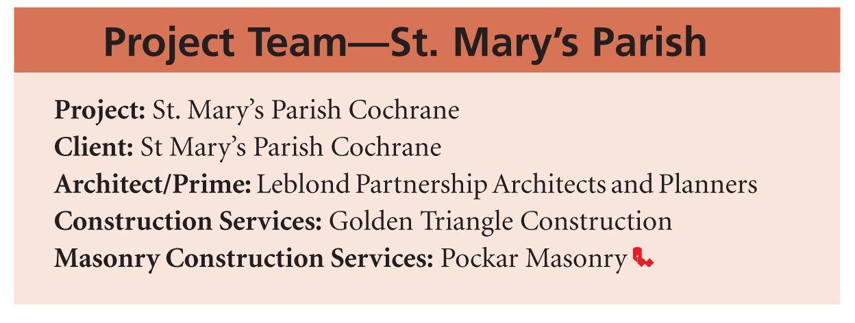
An example of this is explored in the complicated six-wythe recessed and skewed (i.e. wandering) arch at St. Mary’s Parish church in Cochrane, Alta. (Figure 3). Careful design was required to laterally support the arches with the structural steel framing, though lateral loads are also resisted by the arch. As depicted in the details (Figure 4) and photos (Figure 5), considerable planning went into bringing the arch to reality—including arch formwork first constructed in the contractor’s shop before being transported onsite to ensure the formwork would produce the arches as designed.
Load-bearing arches require an understanding of arch design. Although finite element structural analysis programs can assist with the forces generated in the arch from the loading, the masonry must still be designed to adequately resist these forces. The 2014 CSA S304 will likely provide guidelines on the design of structural masonry arches while additional resources include the Brick Institute of America’s (BIA’s) Technical Notes1 and the National Concrete Masonry Associations (NCMA’s) Tek-Aids.2
Veneer arches
Veneer arches have been gaining popularity as a method for providing Old World charm to buildings without load-bearing masonry walls. As buildings in the current construction environment move to lighter sub-structures, masonry arches have adapted to become veneer-based. Often, the structural backup wall is structural steel and steel stud framing. Where a single-wythe masonry veneer arch is employed, steel or wood stud framing can provide a suitable structure for lateral support of the masonry veneer arch.
 Depending on the arch design’s complexity, stud backup wall systems may require careful consideration in place of the studs within the backup wall to accommodate lateral tie spacing that may not necessarily align with the stud spacing—typically, 406 mm (16 in.) on centre (oc).
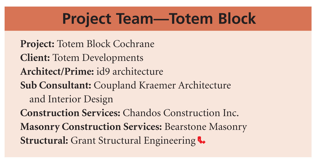
A situation like this occurred during construction of the east elevation of the Totem Block building, also in Cochrane (Figure 6). The cross-section detail of the recessed three-wythe Indiana limestone arch is shown in Figure 7. The area highlighted in green illustrates the void between the stone arch and the steel stud backup. This void was reinforced with 10M reinforcement bent to follow the curvature of the arch, 10M bars placed radally as stirrups, and ties to anchor the entire system to the steel stud backup and filled with pre-bagged 25-MPa concrete. Figure 8 illustrates the steel stud structure behind the arch, while Figure 9 depicts the depth of the three-wythe arch as built.
Ideally, the building will have a concrete masonry unit (CMU) backup wall as opposed to wood or steel stud. This is because a ‘block’ backup wall allows tie placement anywhere needed within the wall’s projection. However, this is not always a feasible solution. An alternative is to use a block backup wall only at the locations backing the masonry veneer arch. The rest of the building can remain steel or wood frame (depending on the original design), yet also have the ability to place veneer ties for the arch where they are needed without complicated stud layouts.
Guidance on the design of a brick veneer arch to support its weight across a given span was provided in BIA’s Technical Note for the design of brick masonry arches. This empirical guideline for brick veneer arches provides prescriptive requirements for three forms of arch.
Segmental arches are limited to less than one-half a circle in curvature, with a rise/span ratio less than one-half, where the skewback angle shall be as small as possible and the wall height above the spring line should be at least 1.3 times the arch radius. The abutment length must be equal to two-thirds of the span length for one surface and one-third the span length for two surfaces.
For semi-circular arches, the smallest arch depth permissible is one-half a brick length where the wall above should be at least 0.9 times the span from spring line and the abutment length should be two-fifths the span length for one surface, and one-fifth the span length for two surfaces.
The last arch form addressed in the empirical design technical note is a Jack arch. This form, also known as a flat arch, is limited to 1800 mm (6 ft) in span if a steel lintel is not used, and must incorporate a skewback of 4.2 mm per 102 mm (½ in. per ft) of span for each 102-mm (4-in.) arch depth. Other requirements include a camber of 1 mm per 100 mm (1/8 in. per ft) of span a minimum arch depth of one unit length and an abutment length equal to a span length for one surface and ½ span length for two surfaces. Although not yet confirmed, it is expected the 2014 CSA S304 will have similar provisions for empirical design of arches within the standard.
One alternative to designing a structural veneer arch is to use an exposed curved steel lintel (Figure 10a) or proprietary concealed steel lintel product for the arch (Figure 10b). This may be necessary if the span exceeds the prescriptive requirements or the abutments are insufficient to provide the necessary support for the arch. Several variations of the concealed lintel configuration exist. Figure 10b demonstrates one configuration of concealed steel lintel products for the arches. Using a concealed lintel provides the appearance of a structural veneer arch, although it is a non-structural arch.


Conclusion
Masonry arches continue to be used as a solution to both form and function, providing structure where needed and creating monumental architecture. The 2014 version of CSA S304 intends to address the design of masonry arches by providing guidance to engineers when these unique structures are incorporated into buildings as either load bearing or non-load-bearing elements. The CSA S304 will be the first standard in the world to include masonry arch design when arch clauses are finalized for the 2014 edition. Although the clauses and tables pertaining to empirical design of masonry arches are expected to be conservative in the 2014 edition of the standard their accuracy is expected to improve in future editions.
Notes
1 For more information, visit www.gobrick.com/portals/25/docs/technical%20notes/tn31.pdf. (back to top)
2 See ncma-br.org/pdfs/103/TEK%2014-14u1.pdf. (back to top)
 Mark D. Hagel, PhD, P.Eng., is the executive director of the Alberta Masonry Council. He holds bachelor’s degrees in actuarial science/applied mathematics and civil engineering, and a doctorate in civil engineering. Hagel was previously employed as a technical services engineer for the Canadian Concrete Masonry Producers Association (CCMPA) and a building envelope engineer and structural engineer with the Calgary office of Halcrow Yolles. Hagel can be reached via e-mail at markhagel@albertamasonrycouncil.ca.
 Monica Guzman M.Sc., B.Eng., is a masonry design coordinator with the Canada Masonry Design Centre (CMDC). She holds bachelor’s and master’s degrees in civil engineering. Guzman provides technical assistance to all masonry designers and to masonry contractors part of the Canadian Masonry Contractors’ Association (CMCA). She was involved in the development of the Masonry Analysis Structural System (MASS) design software. Guzman is a technical committee member for the Canadian Standards Association (CSA) masonry standards. She can be reached by e-mail at mguzman@canadamasonrycentre.com.


