

Introduction: 10 WATT PORTABLE GUITAR AMP WITH DISTORTION


This is my first project here in Instructables....
I am an hobbist having entertainment with chemistry and electronics, and I come frome Italy.
Since I like music and I'm a self-taught guitar player, so I had the idea of projecting a little guitar amplifier, yes small by size and also with little power (but not too much, 10 watt aren't so few!).
The idea come because I have some integrated of the TDA family, and I thougt right for this purpose using the TDA2030. Apart from the wood and the handle that I had already, with the cost of 5-6 euros for electronics components and 10 euros for the loudspeaker it's possible to create a discrete amp....
Step 1: How to Begin...the Structure


If you want start from zero, you must think first of all to the frame of the amplifier.
You can choose the classical DMF right for making panels, even of considerable size, or (like I did) a variety of plywood, quite thick, so to say at least 1.5 cm.
I cutted the the several parts I needed, just to have a final result of a "rectangular box" of 35 cm wide, 20 cm long, 25 cm high, more or less.
After that I proceeded gluing, adding some nail here and there to the panels. I added some screw too, to make the structure more stable and inspected inside (I required 4 screws, but it's better 6). The part most important is the front panel cutted in a circle at the center, to receive the loudspeaker, that can be quite heavy. As you can see from the figure I glued 4 simmetrical little pieces of wood in the inner side of the panel, and there I screwed the speaker, to keep it right firm.
Some holes were needed to receive the connectors and the potentiometers. At this point I faced a problem: since the screws of the connector were shorter than the thickness of the wood I had to mill a little the wood inside of some panels with sanding tips.
To finish, I covered all with adhesive paper, opportunely glued. You can choose any kind or color you like, I put a fake-wood pattern. I covered the front panel too, at the outside, with a generic canvas of brown color in tune with wood color . It would have been better to put a speaker canvas, but I had no one.
To support the whole structure I used a steel handle.
Step 2: Some Electronic Theory....

Before performing the various electronic parts I need to establish the bases of the project.
I built a block diagram illustrating the various stages of the amp. First of all I put what necessary for the right working, and just after I decided to include additional thing.
First of all, a guitar amplifier needs a preamplifier, the TDA2030 I choosed is specific for car radio and therefore alone cannot adapt to the impedance of the guitar signal. For the clean sound is necessary to put a preamp stage before the TDA2030. Between these two stages I put the tone control (followed by the volume control). Some people say it's better put the first before the other, or make an active tone control. In my case I found a good way by using a passive tone with low gain loss, not affecting the quality of the sound.
All these stages require a proper power supply. Here, you need a transformer at least with 2-2,5 A at the secondary with one (or two better) outputs, one of these has to be 24 volt DC. You don't forget the fuse for the transformer before the primary: as a rule of thumb a good value I found is 1 A.
I decided also to equip with a distortion circuit, since most small guitar amp do not have one.
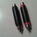
A final add to my project was to place the output for earphones (SEE IMAGE). I used a 6-pin panel jack connector, muting the loudspeaker when the jack is inserted. To get the right impedance at the earphones I inserted a 150 Ω resistor between the connector and the positive pole of the speaker.
Step 3: The Power Supply


I had available a transformer with two outputs, I used each.
It was already equipped with a SPST switch and fuse so I used it as such, changing only the valure of the fuse.
The power supply of the preamplifier and the distortion circuit have a different voltage from that of the power amplifier. The first ones needs 9 Volt to work properly, the other one needs at least 17-18 volt in the single supply version. So I made two distinct circuits to obtain Vcc1 and Vcc2.
For the 9 volt setting (Vcc2), I just took a LM7809 wich can deliver up to 1 A, that's well above the required current from the preamp and the distiortion circuit.
For the TDA2030 circuit instead for better performance I raised a little the voltage up to 22 V (Vcc1), by using the voltage regulator LM317 and setting the variable resistor until the required voltage is reached. Then, to increase the amperage of up to 2-2-5 A I used a NPN power transistor, like TIP41c, holding the load of the remaining current (SEE PHOTO AND IMAGE)
Step 4: The Preamp (clean Sound)

There are many ways to make a guitar preamp. Some are made by complex circuits, but for the purpose of this project a simple JFET or else an opamp, like TL071, TL072, MC4558, LM741 ecc. is enough...
After trying some of these last ones I decided upon the uA741, it has higher gain, a larger bandwidth, lower input current and it's not an expensive chip.
As you see I built this circuit using the opamp in an inverting configuration, with a gain of about 8 in counterphase.
Step 5: The Distortion


At the begin I didn't expect to provide the amplifier of a distortion circuit, because I wanted to make things as simply as possible. But after looking around I found a good (and not complex at all) distortion circuit, based on the LM386 chip.
As you know it is an amplifier integrated, cheap and with good performance.
With the right connections (SEE IMAGE) it can achieve a "gain" of several tens and hundred too, leading to a distorted signal at the output.
To go from clean to distorted sound and vice versa I equipped the amp with a DPDT toggle switch. The schematic is showed in the previous block diagram.
Step 6: The Last Stage of the Amp


The last stage represents the "core" of the device.
The TDA2030 is a low frequency class A - B amplifier, tha can provide up to 14 watt output. The standard scheme of realization of the circuit can be with double or also with the single power supply. In this work I used for convenience the single power supply.
Since this circuit is the most important part, some care is needed in the realization of the PCB and the soldering, especially by the pins of the integrated.
Of course the TDA2030 can become very hot at high volume or after long operation time, so it must be provided with appropriate heatsink.
Before the signal input at the amplifier I provided a volume control, by a 100 K audio log. potentiometer (also 50 K is good) and before that the tone control, consisting of both a high pass filter and a low pass filter, with low-to-moderate loss. I used a 250 K audio pot. (linear) in a single knob configuration to control the tones.
.
Step 7: The Final Look


Wrapping things up, it was a fun experience although a bit long....maybe I could improve something here and there, but as a first experience in the audio panorama it was not so bad....
For those interested here I put the link of the video of the amplifier while working:
Step 8: Post Scriptum

Since someone asked me, I thought a good thing to post the overall schematic with B.O.M. (component list) for a more comprehensible connection drawing.
NOTE: there's a DPDT switch necessary to swap from the clean stage to the distortion stage, and going directly to the input of the final stage (TDA2030). It can be found on the image with numbers from 1 to 6.


![Tim's Mechanical Spider Leg [LU9685-20CU]](https://content.instructables.com/FFB/5R4I/LVKZ6G6R/FFB5R4ILVKZ6G6R.png?auto=webp&crop=1.2%3A1&frame=1&width=306)


