
Safety Factor of Masonry Arches under Gravity Loads
1
Department of Structures for Engineering and Architecture, University of Naples “Federico II”, P.le Tecchio, 80, 80125 Naples, Italy
2
Department of Structures for Engineering and Architecture, University of Naples “Federico II”, Via Claudio 21, 80125 Naples, Italy
*
Author to whom correspondence should be addressed.
Buildings 2022, 12(12), 2059; https://doi.org/10.3390/buildings12122059
Submission received: 27 September 2022
/
Revised: 14 November 2022
/
Accepted: 21 November 2022
/
Published: 24 November 2022
(This article belongs to the Section Building Structures)
Abstract
:In the present paper, a procedure is presented for the evaluation of the safety factor and the limit conditions of masonry arches subject to gravity loadings. The proposed procedure can be considered an extension of Heyman’s method for determining the geometrical safety factor. At variance with Heyman’s method, herein, the analysis of the static safety condition for the arch is performed by means of modified kinematic configurations of the arch obtained by encompassing settlements at the arch constraints. Furthermore, the procedure allows the identification of the critical locations of the hinges in the arch at the limit conditions. Moreover, the present procedure allows the determination of the geometrical vertical displacement that the crown of the arch can accommodate at the safety limit conditions. Finally, the proposed procedure is applied to a real case in order to show its effectiveness. Numerical results are reported and commented on in order to clarify the application of the proposed procedure for the definition of the safety factor of the arched structure and the evaluation of the critical geometrical configuration compatible with the limit conditions of the arch.
1. Introduction
Since the 18th century, the stability of masonry arches has been assessed by using the equilibrium approach, together with the theory of proportions used by ancient builders and by following the indications reported, e.g., in architectural treaties; see, among others A. Palladio [1], L. B. Alberti [2], G. A. Breymann [3].
The research conducted in the 19th century on the strength of materials and continuum mechanics favored the development of methods of analysis for arches based on the stress approach that involves both the set of equilibrium and compatibility equations. However, at that time, such an approach did not fit well to the case of masonry structures, since masonry typically is a two-phase material made of an assemblage of bricks/blocks and mortar, with unilateral non-linear behavior characterized by difficulties and challenges in the material modeling [4,5,6].
For this reason, the second part of the 20th century was characterized by the rediscovery of the equilibrium approach due to the investigations provided by Heyman [7,8,9,10] and the application of the limit analysis theorems from steel structures to masonry arches under vertical loads and with the well-known assumptions on material behavior. In such research works, Heyman brought back the simplicity of equilibrium equations in the study of masonry arches but also provided a powerful tool for predicting the limit conditions of arches stability [11,12,13,14].
Furthermore, Heyman [7,8,9,10] provided an alternative method of assessing the safety of an arch with numerical meaning. According to Heyman [9]: “the statement that an arch is ‘safe’ if it can be shown to contain a proper funicular polygon does not indicate the extent of that safety”. Therefore, he introduced a geometrical factor of safety SF defined by the ratio of the thickness of the arch (t) to the minimum thickness of the arch that contains the line of thrust (tmin):
According to the middle-third rule, the allowable geometrical factor should be equal to 3, but Heyman suggested adopting an allowable value of SF smaller than 3 for practical arch design. Based on the practical rehabilitation of some masonry arches, Heyman stated that an acceptable geometrical factor of 2 might be appropriate for measuring the safety of masonry arches under the design loads.
Subsequently, Huerta [15] confirmed that the usual geometrical factor for arches is 2 and advocated that any master mason would evaluate, just by adopting the actual values of SF ≥ 2, that the arch is not only safe, but it also has a surplus in safety.
The main drawback in using Heyman’s geometrical factor of safety SF consists of the possibility of obtaining a theoretically infinite safety factor in the presence of line of thrust coincident with the center line of the arch.
Furthermore, since Heyman’s geometrical factor of safety is based on the application of the Limit Analysis (LA) approach to rigid bodies, the quality and the texture of brickwork that it is assumed to be of good quality it is not taken into account.
In addition, Heyman’s formulation does not provide any information about the state of deformation and of displacement of the arch; therefore, it cannot be applied in the design of load tests for arched structures. In other words, it does not provide any information about the sensitivity of masonry arches to horizontal displacements occurring at the restraints.
In recent years, alternative approaches have been proposed and used in the literature to overcome these limitations, such as discrete modeling (for instance, see [16,17]) or continuous modeling (see, among others, [18,19,20,21,22]).
In the framework of Heyman’s method, in the present paper, a procedure is proposed for the assessment of a geometric safety factor which also encompasses the effects of horizontal settlements at the arch springing compatible with the static stability of the arch subject to the design loads.
Horizontal displacements may occur at the arch constraints, due to the settlements. In fact, horizontal constraint displacements lead to modified configurations for an arch with modification of the thrust line associated with the fall of the horizontal component of the thrust at the constraints and a subsequent reduction in the safety factor. This process leads to the limit conditions for the arch.
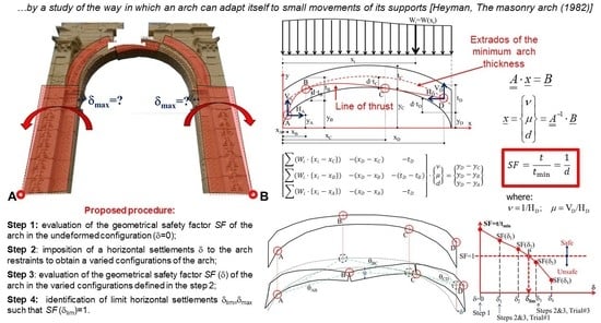
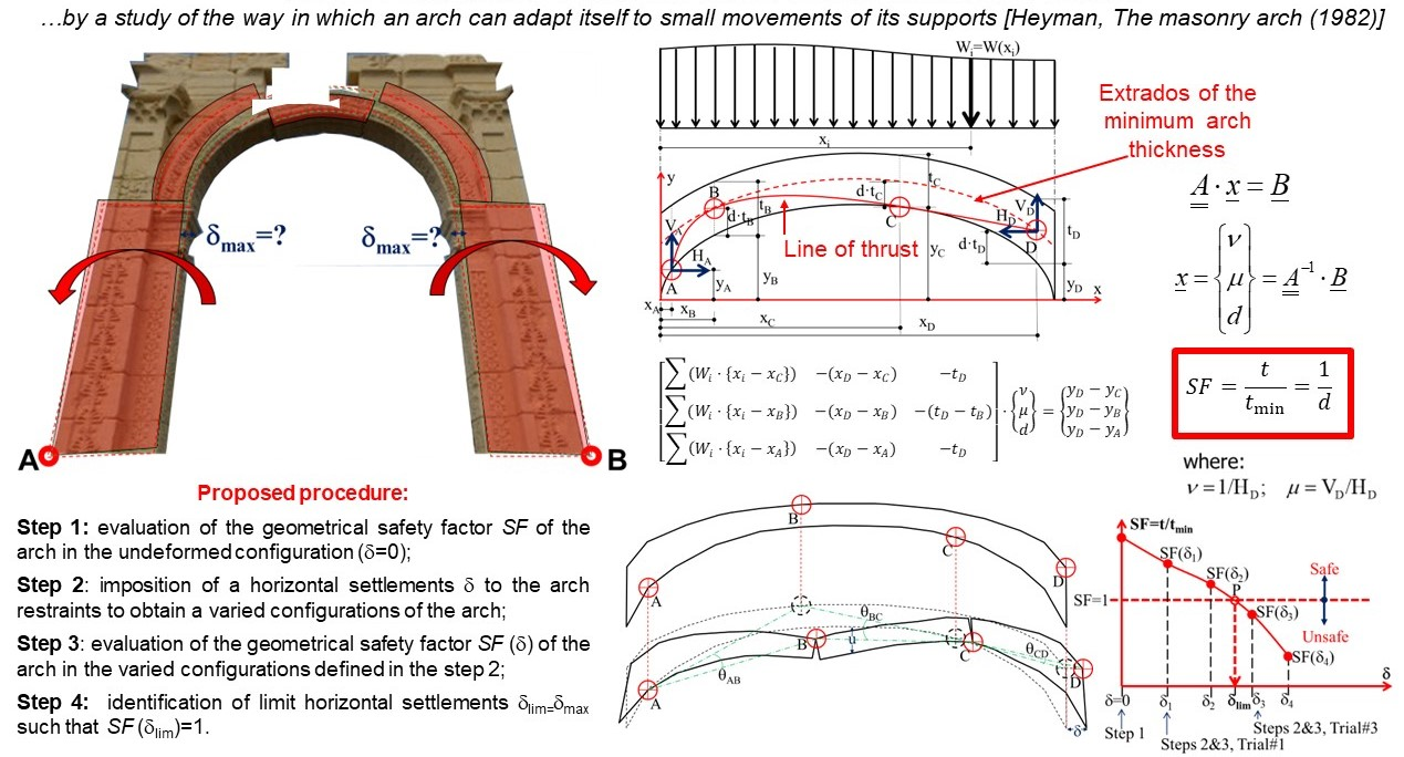
A procedure for the definition of a safety factor is proposed in this paper in order to measure the sensitivity of masonry arched structures under vertical loads, and in order to accommodate—in safe conditions—the horizontal displacements of the arch constraints. The presented procedure can be considered as an extension of the Heyman method, “by considering the ways in which an arch might fail … by a study of the way in which an arch can adapt itself to small movements of its supports”, as suggested by Heyman himself [9]. At variance with Heyman’s method, herein, modified kinematic configurations of the arch are considered by encompassing imposed horizontal displacements at the arch constraints. Varied configurations of the arch are considered by prescribing horizontal displacements at the arch constraints. By applying Heyman’s method on different varied configurations of the arch while approaching to collapse, the limit settlement displacement is determined corresponding to the limit safety condition for the arch, which is when the safety factor is equal to one.
It is noted that the proposed procedure is also useful for identifying the critical locations of the hinges for the arch at collapse, and it is capable of evaluating the geometrical vertical displacement of the crown of the arch at the safety limit conditions. The procedure can be used for the analysis of arches with different shapes. The possible variability in the arch thickness can also be considered, since the arch geometry is given through the cartesian coordinates of the arch intrados and extrados.
An application related to a practical example is also reported in the paper in order to show the effectiveness of the proposed procedure. The results are discussed and commented on in order to show that the procedure is a suitable method for providing the safety factor of masonry arches subject to vertical loadings and for evaluating their limit conditions in terms of allowable horizontal displacements at the springing and of vertical displacement at the crown of the arch.
2. Safety Factor for Arched Masonry Structures during Loading Tests
Under the assumption of the infinite compressive strength of masonry, an arch made of rigid voussoirs can collapse only in the presence of abutments’ spreads. This concept is also remarked on by Como [23], who stated that undeformable arched structures will always be able to sustain applied loads. Therefore, the collapse mechanism cannot occur unless the constraints are displaced through settlements.
If the arch is safe in the undeformed configuration and the constraint is subject to a prescribed horizontal displacement with abutments’ spread, the arch can accommodate itself in a new stable configuration if the horizontal displacement is compatible with the arch geometry and the applied loads or, otherwise, it can collapse.
To better understand this idea, Figure 1a (top) shows a flat arch made of rectangular voussoirs under vertical loads; the structure is not able to support any horizontal displacement δ of the supports, i.e., δlim = 0. On the contrary, the flat arch of Figure 1a (bottom), constructed by using wedge-shaped blocks, can resist a maximum horizontal displacement δ of the supports which is proportional to the arch thickness t, namely: δlim = 2t/tgα.
The question arises for the curved arches of Figure 1b subjected to vertical loadings and horizontal movements of the abutments associated with horizontal displacements of the constraint. It can be observed that an arched structure made of steel balls is not capable of supporting even its own weight. For arches made of different qualities of masonry (bad/medium or good quality) that are stable under the applied vertical loads, it is of interest to evaluate whether they are also stable in the case of imposed displacement at the constraints. Furthermore, it is also of particular interest to assess the limit value δlim of the restraint’s settlement compatible with the static stability of the arch.
From the practitioner’s point of view, the answer to this question can be useful in the experimental tests of masonry arches in order to evaluate the limit conditions of safety of arched structures during the loading operations. It is also of interest to consider that the values that can be measured during experimental tests are typically the displacements of the monitored points of the structure.
Accordingly, looking for an appropriate extension of the geometrical factor of safety SF provided by Heyman (Equation (1)) in the following section, a numerical procedure is provided for the definition of a safety factor that takes into account the varied configurations of the arch in approaching the limit condition of static stability for the arch.
3. Numerical Procedure for Evaluating the Limit Condition for the Stability of the Arch
The limit condition for the stability of a masonry arch with any shape can be established by using the procedure illustrated in the following subsections.
3.1. Definition of Critical Arrangement of Hinges, Evaluation of the Minimum Thickness of the Arch tmin and of the Safety Factor SF
With reference to the arch of Figure 2 subject to the vertical loads W(x), it is possible to adopt the procedure suggested by Heyman [8,9] for evaluating the minimum thickness of the arch tmin, as well as for defining the more critical arrangement of hinges A, B, C and D in the arch development.
Concerning an arbitrary arrangement of four hinges within the development of the arch, from the equilibrium conditions of zero moments around the hinges C, B, and A we have:
where x and y are the Cartesian coordinates of the intrados profile; t(x) is the actual thickness of the arch at the abscissa x; d is the ratio between the minimum thickness of the arch tmin(x) and t(x); VA, HA, VD and HD are the vertical and horizontal reactions of the hinges A and D, respectively; Wi = W(xi) is the vertical load acting at the abscissa xi; {} are the Macaulay brackets.
The three Equations (2)–(4) can be rewritten in the following system of three linear equations:
which can be expressed in the following matrix form:
where:
Let us assume:
The matrix Equation (6) can be written in the following compact form:
whose matrix solution is:
where is the inverse matrix of the matrix .
The solution set (12) also provides the minimum thickness of the arch tmin, that is:
Consequently, the curve representing the extrados profile of the arch with minimum thickness has the Cartesian coordinates: [x; y(x) + tmin(x) = y(x) + d·t(x)], and it is plotted in Figure 2 by using the dashed red line passing at the distance tmin(x) above the intrados of the arch.
Therefore, according to Equations (1) and (13), the geometrical safety factor of the arch is given by:
The correctness of the solution set (12) can be checked by drawing the line of thrust within the arch and then by verifying whether it is both wholly contained within the minimum-thickness arch and passing through the hinges A, B, C and D in their critical locations.
To achieve this aim, the arch of Figure 2 was cut at the abscissa x, and the right side of the structure is reported in Figure 3 together with the applied forces, namely the vertical loads W(x), the reactions VD and HD of the hinge D, and the thrust of the arch N(x) at the cut section.
The analytical equation of the line of thrust can be written by imposing the equilibrium condition of the moments of these forces around the application point of the thrust N(x):
which provides the ordinate yLT(x) of line of thrust at the cut section:
Consequently, by considering Equation (7), the equation of the funicular polygon representing the line of thrust in the arch can be written for any section x as:
3.2. Procedure for Evaluating the Safety Factor and the Limit Conditions for the Stability of the Arch
In the present section, we detail the procedure for the definition of the limit condition for the static stability of the arch and for the evaluation of the safety factor for a masonry arch of arbitrary shape under vertical loadings.
As stated in Section 2, according to Heyman’s assumptions, the collapse of an arch under vertical loadings can only occur in the presence of settlements in the restraints.
Accordingly, from the engineering point of view, the extent of safety for an arch which is stable under the applied vertical loads can be measured through the following procedure:
Step 1: Evaluation of the geometrical safety factor SF of the arch in the undeformed configuration (i.e., considering the as-is arch geometry) by the following sub-steps:
- (a)
- Assuming an initial hinge pattern by placing hinges A, B, C and D within the development of the arch, alternately at the intrados and the extrados, according to the potential failure mechanism that can be activated under the acting loads. The horizontal distances of the hinges can be initially fixed by assuming xA = 0, xB = L/4, xC = 3/4L, xD = L, where L is the internal span of the arch;
- (b)
- Solving the matrix Equation (11), finding the unknown variables (10) and the safety factor corresponding to the assumed hinge pattern through Equation (14);
- (c)
- Varying the location of hinges A, B, C and D to find the arrangement of the more critical hinges by repeating step (b) to maximize parameter d (i.e., for minimizing the safety factor SF according to Equation (14)). This sub-step can be iterated by hand, or even better, it can be implemented in an automatic procedure by using optimization techniques as described by the authors in [24,25,26,27,28];
- (d)
- Checking the correctness of the hinge pattern by tracing the line of thrust in the arch through the analytical solution Equation (17) and then by observing that the line of thrust is both wholly contained within the minimum-thickness arch and passing through hinges A, B, C and D arranged in their critical locations.
Step 2: Imposition of a horizontal settlement δ to the arch springs to obtain a varied configuration of the arch, whose new geometry can be generated from the one of the previous steps by suitably rotating angles θAB, θBC and θCD of the three rigid bodies defined by the critical hinge pattern previously established in sub-step (c) (see Figure 4).
Step 3: Evaluation of the geometrical safety factor SF(δ) of the arch in the varied configuration defined in step 2. The analysis of the arch in the varied configuration can be performed by using the same sub-steps (a)–(d) as illustrated above.
In Figure 5, the safety factor (SF) is plotted as a function of the horizontal settlement (δ) imposed at the right constraint. The safety factor (SF) is obtained as a function of the horizontal settlement (δ) by iterating steps 2 and 3 several times through the imposition of different values of the horizontal settlements, respectively, denoted in the figure as δ1, δ2, δ3 and δ4. The horizontal dashed line corresponding to SF = 1 represents the limit condition for the safety of the arch. The area of the diagram located above this line is characterized by SF > 1, and therefore, the arch is considered to be in a safe condition, since the arch thickness contains the line of thrust (i.e., t > tmin). The SF-δ curve intersects the horizontal dashed line SF = 1 at the point P corresponding to the maximum value of the imposed horizontal settlement δlim that the arch can accommodate in safety under the applied loads.
4. Application of the Procedure to a Real Case: The Safety Factor of a Cloister Vault of the Palazzo Caracciolo di Avellino in Naples
In order to emphasize the effectiveness and usefulness of the proposed procedure, in this section, we illustrate its applicability to a real case for the structural analysis of an historical masonry building.
Accordingly, the application of the proposed procedure for evaluating the geometrical safety factor SF of arches is herein applied to the real case of a cloister vault of the Palazzo Caracciolo di Avellino in Naples, Italy (see Figure 6).
This application is necessary as a preliminary analysis in the design of the experimental loading tests to be performed after the strengthening works of the vault.
In detail, four static load tests are performed on the vault:
- Test #1, consisting of 9 kN/m2 distributed load on the whole vault;
- Test #2, consisting of 9 kN/m2 distributed load on half of the vault and 1.5 kN/m2 distributed load on the remaining half of the vault;
- Test #3, consisting of 40 kN pointed load applied on the crown of the vault;
- Test #4, consisting of 40 kN pointed load applied in an asymmetrical position on the vault.
The three-dimensional analyses of the tested vault are illustrated in [29]. Herein, the cloister vault is studied by considering the two main arches along the x and y directions depicted in Figure 6, in accordance with the slicing technique that is typically used for the analysis of vaults and domes. Accordingly, the loads acting on the vault were divided according to the rule of the fourth power of the span length of the main arches.
For the sake of brevity, we only illustrate the analysis of loading test #2 by reporting the results of the analysis in the diagrams of Figure 7, Figure 8, Figure 9 and Figure 10. In detail, Figure 7 and Figure 9 show the analysis of the geometrical safety factor SF evaluated for the arches in the x and y direction, respectively, for different values of the horizontal settlement δ imposed at the right constraint. The line of thrust passing through the critical locations of hinges A, B, C and D are also provided in Figure 7 and Figure 9 with a red continuous line, while the extrados of the minimum-thickness arch was plotted with a red dashed line.
In Figure 8 (top) and Figure 10 (top), the corresponding SF-δ curve is plotted by using the same format adopted in Figure 5. Furthermore, in Figure 8 (bottom) and Figure 10 (bottom), the geometrical vertical displacement v of the crown of the arch is plotted as a function of the horizontal settlement δ imposed at the right constraint of the arch.
The geometrical safety factor SF is evaluated by considering the arches in their undeformed configurations (step 1 of procedure in Section 3.2) and in four varied configurations (steps 2 and 3 of procedure in Section 3.2) obtained by imposing four different values of the horizontal settlement to the right constraint of the arches, namely: δ1 = 30 mm, δ2 = 40 mm, δ3 = 50 mm and δ4 = 100 mm.
By analyzing the arch in the x-direction, from the diagrams of Figure 7 and Figure 8, it is noted that the safety factor ranges from SF = 1.16, in the undeformed configuration (δ = 0), to the limit condition of the safety illustrated in Figure 7c, where the extrados of the minimum thickness for the arch is overlapped to the actual extrados of the arch (i.e., tmin(x) = t(x)), and therefore, the value of the safety factor is SF~1.
The reaching of the limit condition for the stability of the arch is furtherly highlighted in Figure 8 (top) at point P, where the condition SF = 1 corresponds to the limit value δlim = δ2 = 40 mm of the horizontal settlement imposed at the constraint and, respectively, in Figure 8 (bottom) at point P, where the geometrical vertical displacement of the crown of the arch at the limit condition is vlim = 30 mm.
On the contrary, the analyses of the deformed arch under imposed settlements greater than δlim = δ2 = 40 mm, namely δ3 = 50 mm and δ4 = 100 mm, provide unsafe conditions of stability, with required minimum thickness of the arch greater than the actual thickness, and consequently, with values of safety factor that range from SF = 0.91 to SF = 0.78.
Similar remarks can be made for the arch in the y-direction by analyzing the diagrams in Figure 9 and Figure 10, where it is noted that the limit condition of safety is reached under imposed settlement lower than δ1 = 30 mm; see Figure 9b. In fact, the horizontal line of Figure 10 (top), corresponding to the limit condition of safety SF = 1, intersects the curve at the limit value for the horizontal settlement imposed at the constraint given by δlim = 24 mm. For this limit value of the horizontal settlement imposed at the constraint, the corresponding value of geometrical vertical displacement of the crown of the arch is, respectively, determined at the limit condition as vlim = 40 mm; see Figure 10 (bottom).
The above numerical results show that, during the adopted loading test #2, the considered segmental vault can be considered ‘safe’, in the sense of the limit conditions provided by Heyman [9], if the horizontal settlement of the constraints at the springings is lower than δ = 24 mm and, at the same time, if the vertical displacement of the crown of the arch is lower than v = 30 mm.
5. Conclusions
A procedure for the assessment of a geometric safety factor SF is proposed in this paper in order to measure the level of safety in masonry arched structures under vertical loads by evaluating the maximum horizontal settlement δlim of the constraints that is compatible with the stability of the arch under the design loads.
The present procedure for the evaluation of the geometric safety factor can be considered an evolution of Heyman’s method, since it is applied on varied configurations of the masonry arch subjected to imposed displacements at the constraints. The procedure is articulated in three main steps: (1) evaluation of the geometrical safety factor SF of the arch in the undeformed configuration SF(δ = 0); (2) imposition of an horizontal settlement δ to the arch constraint; (3) evaluation of the geometrical safety factor SF(δ) of the arch in the varied configuration.
The iterative application of steps (2) and (3) of the procedure by considering different values of the imposed displacement δ allows us to define the potential failure mechanism which can be activated on the arch subjected to increasing imposed horizontal settlements at the constraints. Moreover, the proposed procedure allows us to identify the critical arrangement of the hinges in the arch and the maximum geometrical displacements that the arch can sustain at the limit conditions. The proposed procedure can be applied to any shape of the arch, i.e., circular, pointed, multicentered shapes, regardless of length-span and angle of embrace. The variability in the arch thickness can also be treated within the proposed procedure.
A practical application of the proposed procedure has also been provided by showing the suitable procedure for the evaluation of the geometric safety factor SF for the design of the experimental loading tests performed on a segmental masonry vault of Palazzo Caracciolo di Avellino in Naples (Italy).
The prospective research work on the present research topic will consider the constitutive behavior of the material and hence the analysis with the Finite Element Method. Accordingly, a Finite Element Analysis of the considered case study will be the object of future research work.
Author Contributions
Conceptualization, G.B. and A.D.L.; methodology, G.B. and A.D.L.; validation, G.B., F.D.A. and A.D.L.; formal analysis, G.B. and F.D.A.; investigation, G.B., F.D.A. and A.D.L.; resources, G.B.; data curation, G.B.; writing—original draft preparation, G.B.; writing—review and editing, G.B. and F.D.A.; visualization, G.B. and F.D.A.; supervision, G.B., F.D.A. and A.D.L. All authors have read and agreed to the published version of the manuscript.
Funding
This research was funded by project DPC-ReLUIS 2022–2023 in the context of the topics of WP5 “Interventi di rapida esecuzione a basso impatto ed integrati” and WP10 “Contributi normativi”.
Data Availability Statement
The raw/processed data used in the present research work are part of an ongoing research project.
Conflicts of Interest
The authors declare no conflict of interest.
References
- Palladio, A. I Quattro Libri Dell’architettura; Domenico de’ Franceschi: Venice, Italy, 1570. (In Italian) [Google Scholar]
- Alberti, L.A. De re Aedificatoria; Nicolò di Lorenzo: Firenze, Italy, 1485. [Google Scholar]
- Breymann, G.A. Archi—Volte—Cupole, Vol II; Antica Casa Editrice Dottor Francesco Vallardi: Milan, Italy, 1885. (In Italian) [Google Scholar]
- Ou, W.; Chen, X.; Chan, A.; Cheng, Y.; Wang, H. FDEM Simulation on the Failure Behavior of Historic Masonry Heritages Subjected to Differential Settlement. Buildings 2022, 12, 1592. [Google Scholar] [CrossRef]
- Chisari, C.; Cacace, D.; De Matteis, G. Parametric Investigation on the Effectiveness of FRM-Retrofitting in Masonry Buttressed Arches. Buildings 2021, 11, 406. [Google Scholar] [CrossRef]
- Pantò, B.; Cannizzaro, F.; Caddemi, S.; Caliò, I.; Chácara, C.; Lourenço, P.B. Nonlinear Modelling of Curved Masonry Structures after Seismic Retrofit through FRP Reinforcing. Buildings 2017, 7, 79. [Google Scholar] [CrossRef] [Green Version]
- Heyman, J. The Stone Skeleton. Int. J. Solids Struct. 1966, 2, 249–256. [Google Scholar] [CrossRef]
- Heyman, J. The Safety of Masonry Arch. Int. J. Mech. Sci. 1969, 11, 363–382. [Google Scholar] [CrossRef]
- Heyman, J. The Masonry Arch; Ellis Horwood Ltd.: Chinchester, UK, 1982. [Google Scholar]
- Heyman, J. The Stone Skeleton; Cambridge University Press: Cambridge, UK, 1995. [Google Scholar]
- Block, P.; Ciblac, T.; John Ochsendorf, J. Real-time limit analysis of vaulted masonry buildings. Comput. Struct. 2006, 84, 1841–1852. [Google Scholar] [CrossRef]
- Fraternali, F. A thrust network approach to the equilibrium problem of unreinforced masonry vaults via polyhedral stress functions. Mech. Res. Commun. 2010, 37, 198–204. [Google Scholar] [CrossRef]
- Marmo, F.; Rosati, L. Reformulation and extension of the thrust network analysis. Comput. Struct. 2017, 182, 104–118. [Google Scholar] [CrossRef]
- Maia Avelino, R.; Iannuzzo, A.; Van Mele, T.; Block, P. Assessing the safety of vaulted masonry structures using thrust network analysis. Comput. Struct. 2021, 257, 106647. [Google Scholar] [CrossRef]
- Huerta, S. Galileo was wrong: The geometrical design of masonry arches. Nexus Netw. J. 2006, 8, 25–52. [Google Scholar] [CrossRef]
- Lemos, J.V. Discrete element modelling of masonry structures. Int. J. Archit. Herit. 2007, 1, 90–213. [Google Scholar] [CrossRef]
- Baggio, C.; Trovalusci, P. Limit analysis for no-tension and frictional three-dimensional discrete systems. Mech. Struct. Mach. 1998, 26, 287–304. [Google Scholar] [CrossRef]
- Anthoine, A. Derivation of the in-plane elastic characteristics of masonry through homogenization theory. Comput. Struct. 2007, 85, 1321–1330. [Google Scholar] [CrossRef]
- Gambarotta, G.; Lagomarsino, S. Damage models for the seismic response of brick masonry shear walls. Part II: The continuum model and its applications. Earthq. Eng. Struct. Dyn. 1997, 26, 441–462. [Google Scholar] [CrossRef]
- Luciano, R.; Sacco, E. Homogenization technique and damage model for old masonry material. Int. J. Solids Struct. 1997, 34, 3191–3208. [Google Scholar] [CrossRef]
- Zucchini, A.; Lourenço, P.B. A micro-mechanical model for the homogenization of masonry. Int. J. Solids Struct. 2002, 39, 3233–3255. [Google Scholar] [CrossRef]
- Angelillo, M. Constitutive relations for no-tension materials. Meccanica 1993, 28, 195–202. [Google Scholar] [CrossRef]
- Como, M. Statics of Historic Masonry Constructions; Springer: Berlin/Heidelberg, Germany, 2013. [Google Scholar]
- Brandonisio, G.; Mele, E.; De Luca, A. Limit analysis of masonry circular buttressed arches under horizontal loads. Meccanica 2017, 52, 2547–2565. [Google Scholar] [CrossRef]
- Brandonisio, G.; Mele, E.; De Luca, A. Seismic Capacity of URM Buttressed Arches. In Proceedings of the 23rd Conference of the Italian Association of Theoretical and Applied Mechanics, Salerno, Italy, 4–7 September 2017; Volume 2, pp. 1555–1569. [Google Scholar]
- Brandonisio, G.; Angelillo, M.; De Luca, A. Seismic capacity of buttressed masonry arches. Eng. Struct. 2020, 215, 110661. [Google Scholar] [CrossRef]
- Brandonisio, G.; De Luca, A. Influence of Geometry on Seismic Capacity of Circular Buttressed Arches. J. Mech. Mater. Struct. 2019, 14, 645–661. [Google Scholar] [CrossRef]
- Brandonisio, G.; De Luca, A. Analytical modelling for the seismic assessment of pointed arches supported by buttresses. Int. J. Mason. Res. Innov. 2021, 6, 384–404. [Google Scholar] [CrossRef]
- Gesualdo, A.; Brandonisio, G.; De-Luca, A.; Iannuzzo, A.; Montanino, A.; Olivieri, C. Limit Analysis of cloister vaults: The case study of Palazzo Caracciolo di Avellino. J. Mech. Mater. Struct. 2019, 14, 739–750. [Google Scholar] [CrossRef]
Figure 1.
Maximum horizontal displacement δlim of (a) flat and (b) curved arches with different qualities of masonry.
Figure 1.
Maximum horizontal displacement δlim of (a) flat and (b) curved arches with different qualities of masonry.

Figure 2.
Equilibrium of a masonry arch under vertical loads W(x), definition of the pressure line and location of hinges.
Figure 2.
Equilibrium of a masonry arch under vertical loads W(x), definition of the pressure line and location of hinges.

Figure 3.
Line of thrust in the arch.

Figure 4.
Varied geometrical configuration of the arch due to the horizontal settlement δ imposed at the right constraint.
Figure 4.
Varied geometrical configuration of the arch due to the horizontal settlement δ imposed at the right constraint.

Figure 5.
Safety factor (SF) versus the horizontal settlement (δ) imposed at the right constraint of the arch.
Figure 5.
Safety factor (SF) versus the horizontal settlement (δ) imposed at the right constraint of the arch.

Figure 6.
Palazzo Caracciolo di Avellino. Vertical section of the masonry palace (top); plan of the masonry palace (middle); and examined cloister vault (bottom center). The examined cloister vault is divided into the two main arches along the x-direction (bottom left) and y-direction (bottom right).

Figure 7.
Evolution of geometrical safety factor SF for the arch in x-direction for different values of the horizontal settlement δ imposed at the right constraint of the arch: (a) δ = 0; (b) δ = 3 cm; (c) δ = 4 cm; (d) δ = 5 cm; and (e) δ = 10 cm.
Figure 7.
Evolution of geometrical safety factor SF for the arch in x-direction for different values of the horizontal settlement δ imposed at the right constraint of the arch: (a) δ = 0; (b) δ = 3 cm; (c) δ = 4 cm; (d) δ = 5 cm; and (e) δ = 10 cm.

Figure 8.
Plot of the geometrical safety factor SF (top) and of the geometrical vertical displacement v of the crown of the arch (bottom) versus the horizontal settlement δ imposed to the right constraint of the arch in the load test #2 for the arch in x-direction.
Figure 8.
Plot of the geometrical safety factor SF (top) and of the geometrical vertical displacement v of the crown of the arch (bottom) versus the horizontal settlement δ imposed to the right constraint of the arch in the load test #2 for the arch in x-direction.

Figure 9.
Evolution of geometrical safety factor SF for the arch in y-direction for different values of the horizontal settlement δ imposed at the right constraint of the arch: (a) δ = 0; (b) δ = 3 cm; (c) δ = 4 cm; (d) δ = 5 cm; and (e) δ = 10 cm.
Figure 9.
Evolution of geometrical safety factor SF for the arch in y-direction for different values of the horizontal settlement δ imposed at the right constraint of the arch: (a) δ = 0; (b) δ = 3 cm; (c) δ = 4 cm; (d) δ = 5 cm; and (e) δ = 10 cm.

Figure 10.
Plot of the geometrical safety factor SF (top) and of the geometrical vertical displacement v of the crown of the arch (bottom) versus the horizontal settlement δ imposed to the right constraint of the arch in the load test #2 for the arch in y-direction.
Figure 10.
Plot of the geometrical safety factor SF (top) and of the geometrical vertical displacement v of the crown of the arch (bottom) versus the horizontal settlement δ imposed to the right constraint of the arch in the load test #2 for the arch in y-direction.

Publisher’s Note: MDPI stays neutral with regard to jurisdictional claims in published maps and institutional affiliations. |
© 2022 by the authors. Licensee MDPI, Basel, Switzerland. This article is an open access article distributed under the terms and conditions of the Creative Commons Attribution (CC BY) license (https://creativecommons.org/licenses/by/4.0/).
Share and Cite
MDPI and ACS Style
Brandonisio, G.; De Angelis, F.; De Luca, A. Safety Factor of Masonry Arches under Gravity Loads. Buildings 2022, 12, 2059. https://doi.org/10.3390/buildings12122059
AMA Style
Brandonisio G, De Angelis F, De Luca A. Safety Factor of Masonry Arches under Gravity Loads. Buildings. 2022; 12(12):2059. https://doi.org/10.3390/buildings12122059
Chicago/Turabian StyleBrandonisio, Giuseppe, Fabio De Angelis, and Antonello De Luca. 2022. "Safety Factor of Masonry Arches under Gravity Loads" Buildings 12, no. 12: 2059. https://doi.org/10.3390/buildings12122059
Note that from the first issue of 2016, this journal uses article numbers instead of page numbers. See further details here.